|
Ref. theory |
π-matrix, Scientific Reports volume 5, Article number: 10571 (2015) |
|
Thesis Citation |
Modeling Multi-Magnet Networks Interacting Via Spin Currents (Srikant Srinivasan1,2, Vinh Diep1, Behtash Behin-Aein1,3, Angik Sarkar1 and Supriyo Datta1,1School of Electrical & Computer Engineering, Purdue University, West Lafayette, IN-479072Dept. of Mat. Sci. & Eng., Iowa State University, Ames, IA-50011, 3Globalfoundries Inc.) |
|
Implications |
easly make simulation tool for design electronics device |
If you are not programmer or computational scientist, you cannot simulate some predictions of scientific experiment results.
But with a little works of coding, you can achieve a great simulation tool of your experiment.
First, when you study solid physics or material for electric device, you should find correlation between voltage and your physics model.
The electric device is only composed of voltage and current in the end. So all your physics model converts to voltage and current.
And you just apply all equation to voltage-current law.
For example, The thesis "Modeling Multi-Magnet Networks Interacting Via Spin Currents" makes spintronics simulation tool for electric device.
The first assumption is there is two spin states, and each have it's own current.
The second assumption is each spin state can convert other spin state.
So the model have two current lines, and interconnect line that links two current lines.
One current line is written in terms of "u", and the other is "d".
Interconnect line is written by "sf" because changing spin state is called "Spin flip".
Than the circuit is like the picture below.

Than you can set ohm's law,

It is called π-matrix. Than we just set resistances and conductances by spintronics equations.
(It does not make sense to apply the second equation in spintronics physics!! Why does spin filp depend on spin potential(node voltage).)
In that equation, it is not intuitive to use fermi level.
So we can eliminate Fermi level term and make that equation to matrix.

In Spintronics, there are two physics part, one is charge part, the other is spin part.
Using above equation, we can seperate two parts because sum of all spin current is charge current and subtact two spin component is psin current. The latter's principle is from spin polarization. Look at the equation below (subscripts "c" and "s" refer to charge and spin respectively)

The division of two is from the meaning that the spin up and down voltage is just node voltage, not spin voltage. The Vs does not represent spin voltage. Don't care about Vu, Vd, Vs's meaning, just look at Vc.
The real linking between terms and meaning is later work. Than we can derive some equation.

When we define the spin diffusion length as a relation that

, we can conbine above equation to

.
For solve this equation, we have to get parameter about resistivity 

, and boundary voltage

. After we get the result of this differential equation, we can apply it to upper equation. We can get

In here, ΔV is the material potential difference between L. Vs1 is input voltage at the material. And

.
So, we define some node potential and resistance of spin. Only spin current, spin diffustion length and input-output charge voltage is real. In fact relation
is also not clear beacause r and g is very unclear. in real world.
The spin voltage is not real spin voltage but is a parameter for spin current and spin flip.
That is why, i use different equation below, unlike the thesis for expandability.

Like this, we can reduce unclear part as possible.
I'll show the application of this equation to model here
When some new theory announced in the world, i'm worried about how to apply this theory to my device.
These theory include new material, new physics mechanism, then I must optimize those things.
One day, i found this thesis named "Modular Approach to Spintronics" then i can found solution about my problem.
In this thesis, there is simulation method for easily adjust new theory to spintronics device.
It is very important to engineer, because engineers can not do material and theoretical simulation all the time.
The thesis method convert spintronics' complex physical theory to functional building block.
By this method, you can use module which is made by functional building block for spintronics circuit simulation.
You can predict your device before fabrication.
The researchers design rules between each modules.
Module simulation's most big advantage is engineer does not need to understand deep physical theory for designing spintronics device.
The basic equation of modular simulation for spintronics is posted in Make device simulation even if you are not programer.
With the equation
, I can make simpe simulation tool for spintronics.
The first thing is Non-magnetic channel.
Non-magnetic energy diagram is like below picture.

It has symmetry energy diatram of spin states. So,

!!!!!
Than the above equation can be changed like

This equation's circuit is like this

And the thesis mantion that the ground in picture is not a real ground but rather a virtual 'spin' ground for spin current
Next is Ferro magnet.
In Ferromagnet, the density of state is different by spin state like below picture.

The resistance relation is

. So we can use just original equation

More explanation is in the post "Make device simulation even if you are not programer."
Than how about interface of Non-magnet and Ferro-manget.
The mechanism of interface effect is not explainable yet. So we can broadly set different resistance of spin resistance
as below picture.
For example, in insulator, the tunneling process largely depend on neighbors density of state.(Suppose the insulator's thickness is super thin L<<<<<λ)
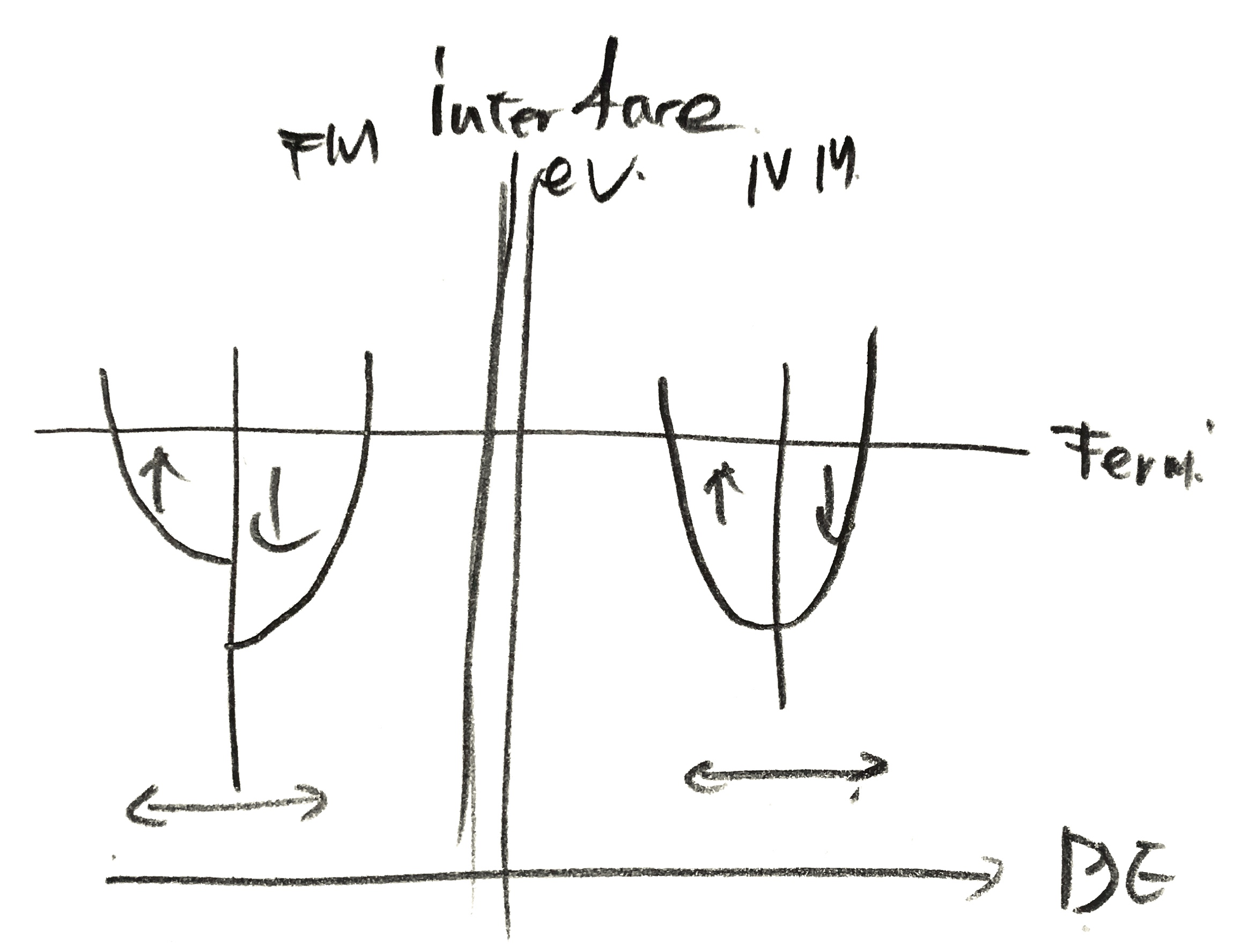
So in tunel barrier, Since barrier's thickness is shorter than spin flip length, There is no spin flip.
It means that

And we can set conductance of tunneling g. Amount of spin state that tunneling successfully, is depend on polarization of each side of insulator. The thesis call this quailty "efdective spin polarization" P.
In fact the 'P' can not be explained only by this mechanism. So, we can get

Now, we are ready to make modeling tool for spintronics!!
Before calulate, we seperate node voltate as

And than, we can apply current conservation laws.(The basic circuit law. It also called Kirchhoff's Current Law, (KCL))
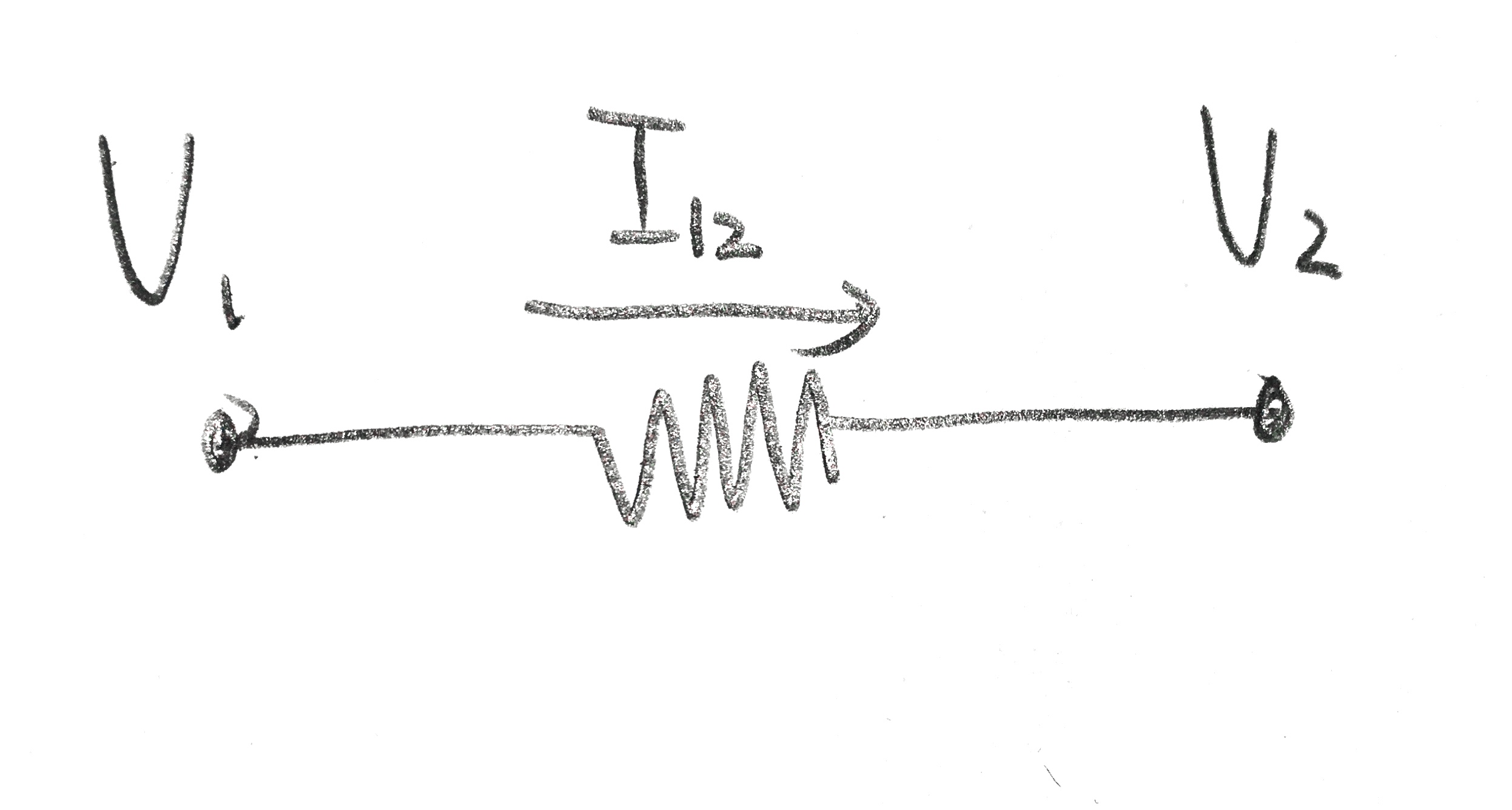
If each node's name is V1, V2 that has charge and spin component together, the major equation convert like

We can apply it to all node. But one thing is different from electronic circuit KCL, that a current is not a resistance current, but a current that spread out from a node.
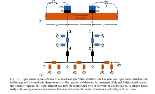
So we should check all the node in circuit.
(the picture's ref is the thesis "Modeling Multi-Magnet Networks Interacting Via Spin Currents (Srikant Srinivasan1,2, Vinh Diep1, Behtash Behin-Aein1,3, Angik Sarkar1 and Supriyo Datta1,1School of Electrical & Computer Engineering, Purdue University, West Lafayette, IN-479072Dept. of Mat. Sci. & Eng., Iowa State University, Ames, IA-50011, 3Globalfoundries Inc.)")
For example, if we check node 5 ,there are node 5 to node 2 current, node 5 to node 6 current, and node 5 to node 2 current.
So when we make this circuits relation.(it also from above thesis)
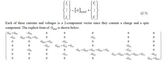
You can make some code for calculate this. And then if source of this circuit is current source, it is (14x1) matrix with (1, spin current, 0, 0, 0, 0, ...)
To get voltage in each node, you just dived above matrix by current.
We can extend into 4-component
that has information of 3D spin direction. So, we should change 2-component equation to 4-component like this.

Before we apply this, we should think that each direction's spin state have diferent property in some material.
The non-magnet material does not distinguish between x, y and z components of spin.
But ferro-magnet material do.
So, Non-magnet material have conductance like

But ferromagnetic has easy axis for one direction from its demagnetization or crystal structure. So we seperate ferromagnet by two components interface(L<λ) and bulk(L>λ). In ferromagnet, we assume that easy axis is 'z' direction.
In bulk region, the hard axis spin state become '0'. (I think it is not....So i'll change it later)
The thesis "Modeling Multi-Magnet Networks Interacting Via Spin Currents (Srikant Srinivasan1,2, Vinh Diep1, Behtash Behin-Aein1,3, Angik Sarkar1 and Supriyo Datta1,1School of Electrical & Computer Engineering, Purdue University, West Lafayette, IN-479072Dept. of Mat. Sci. & Eng., Iowa State University, Ames, IA-50011, 3Globalfoundries Inc.)" specify that "it is valid for thickness greater than a few nanometers in such materials".
Then the equation is like this

The g is for the reflect of another direction spin current that relate with relaxation time of transverse spins. it can be tought like eliminate path.
Than how about interface? The term 'interface' refers the first few monolayer of magnet material. We can easily think scattering theory(But we have to enhance the interface theory in here), so we apply it.
In fact, the spin of spintronics is derived by quantum mechanics. So it exactly means wave function that have probabilities, transmission and reflection.
So, at the interface, there are transmission and reflection coefficients.(Each of those are τ, ρ)

Than we can set a matrix about it.

In this case, the current can be represented by the posibility of current. When this posibility mutiply with charge, then it can be the current.
Non magnetic material's output current can be written

Here, the "f^N" and "f^F" are just some variable, don't have meaning.... we have to find this meaning... some people think it relative with quasi fermi level.
So the real current is like this

In this form, we want to seperate the charge and spin. For this purposel, we use density matrix.

Then, when we trace the "f", it can draw part of charge current, or when we trace "f·σ", we can get spin current component. In here we should keep our eyes on that spin has only z component, we must change it later.
In ferromagnet we use

.
We can convert all parameter as density matrix. Before convert this, We define the term

as the reflection and transmission coefficients respectively.

Later we use only t & r intead of τ & ρ. In here, in previous post " Make device simulation even if you are not programer.", we make

So, we can organize the above expression

In this case, how about t?????? We also should find this parameter's meaning.
All we have to do is just simplication of above equation.
When we simplify this equation, it can be so long. From this point, we define some variable and apply it.
The notions don't have meaning in this time.
There are some notions.

Then we can simplify all current euqation.

It is end.
With this current we can get anything about circuit.
If we want charge current, we just trace this current. Or if we want spin current we just trace this current matrix with σ.

Then we can get final equation.

Then is done? No, at first we have just a posiblity of one energy level.
We should deal with all energies for applied voltage.
The posibility term "f" is the posibility of one energy from one wavefunction.
So when we apply votage V=-μ/q, the posibility can form like

With this fomular, we can intergrate current with all energy level.

Why T and P are not change its value as the energy changed?? just variable??
But it is not enough. The lack of this equation is it is just the current per conducting mode. We don't know what exactly r value, so we should sum all of it and compare with the experiment result.
With this, when we express equation in the matrix form, it is

In here

and , if we assume a ballistic interface, the thesis "Modeling Multi-Magnet Networks Interacting Via Spin Currents (Srikant Srinivasan1,2, Vinh Diep1, Behtash Behin-Aein1,3, Angik Sarkar1 and Supriyo Datta1,1School of Electrical & Computer Engineering, Purdue University, West Lafayette, IN-479072Dept. of Mat. Sci. & Eng., Iowa State University, Ames, IA-50011, 3Globalfoundries Inc.)" say

the M is the total number of conducting modes at the interface. And above aprroximation means the interface conductance(the thesis say....(why?)) And for simplification we define

Then the final equation can be drived

In the above thesis, the M is the number of conducting modes at the interface. Exact value is

and k is the wave vector.
In spintronics theory, the spin torque have twe torque, one is Slonczewski term(Dampling like torque) the other is field like torque. We don't deal with spin torque theory. Just show discribe picture.
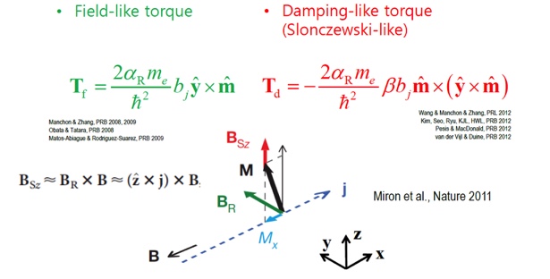
In that matrix, Field like torque that change the magnetic moment's direction is off-diagonal element.
However, the Slonczewski-like torque doesn't change magnetic moment's direction, so it can be the parts of diagonal elements.
In addition, the easy axis can not always be z axis. So we easily take the situation that there are different easy axis in one circuit as two ferromagnet in one circuit. In this case, we can change direction with operator. If we change easy axis, we just only change matrix G. There can be operator to change easy axis like this equation.

Very intuitively, we can think this operator is rotation operator, So in this thesis use the Rodrigues Rotation formula. For the general case, we change the easy axis m1 to m2

Unfortunately, it doesn't meet with spintronics theory. In spintronics there are some essential major theory. One is Landau-Lifshitz-Gilbert(LLG) equation. So now you apply this equation. Even though it is not essential, we have to apply new theory to this simulation tool later.
The LLG equation is about spin information processed in the nanomagnet material like soin torque switching. The damping torque and field like torque i mention above also include in LLG equation.
The thesis in here assumed that the magnets are monodomain.(Later we have to fix it for memristor or skyrmion)
The LLG equation is

The more specific of this equation's part is posted in The latest Landau-Lifshitz-Gilbert(LLG) equation!!!(every time i fix it!!)
For simulation in this thesis, m fixed as monodomain magnetization, and γ which called as the gyromagnetic ratio is 17.6Mhz/Oe. Other term: α is the the Gilbert damping parameter(we can get this parameter by experiment.), q is just charge of an electron, Ns is the number of spin in magnet that is from

. In here Ms is saturation magnetization we can easily see in hystersis loop, Ω is Volume, μ is Bohr magnetron.
But the Most important part is H that represents magnetic field in magnet which include both internal and external field.
The magnetic film has two internal field because of its structure. One is in-plane field, that represent the spin arrow is in the plane, the other is out of plane that ths spin arrow form across the plane.
So H can represent by both internal uniaxial anisotropy and out of plane demagnetizing effective field.
If the easy axis is z then,

.
The above spin circuit can only represent steady state of spin current. But LLG is dynamical state.
But we can change spin circuit to dynamics because it is computer program code!! Just change some code lines. The LLG is only form magnetization m. So The new simulation tool just change magnetizaion state many times with LLG equation.
It take until the final steady state come out.
'스핀트로닉스' 카테고리의 다른 글
| 스핀파(spin wave) _spin pumping, spin seebeck, magnon (4) | 2019.06.07 |
|---|---|
| 자성체(magnetic material)_강반자성체 AFM(antiferromagnetic), 강자성체 FM(ferromagnetic), paramagnetic, diamagnetic, 자화에너지 (0) | 2019.06.07 |
| Pole and Current Model (0) | 2019.04.25 |
| 전자석 (0) | 2019.04.25 |
| 스핀 홀 효과(spin hall effect, SHE)_Anomalous Hall effect(AHE), ISHE (6) | 2018.09.05 |


